


CNC Router
Educational Success Stories
 Affordable Precision Educational CNC Router Affordable Precision Educational CNC RoutereMail us at technosales@technocnc.com |
A CAD/CAM/CNC-Based Process
Recent
innovations in hardware and software have opened new horizons in
the way technology educators can approach the curriculum. As our world becomes increasingly more high tech, fast
paced, and competitive, many middle and high school teachers have
decided to update parts of their manual technology programs with
automated technology. One good example involves transforming the
C02 car
curriculum into a CAD/CAM/CNC based process.
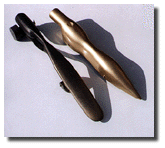
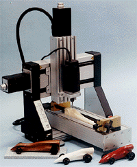
Benefits of CNC. Students will work hard for something they want to own. Few at the middle school level have the carving skills needed to produce a good product from raw stock. Some lose interest when they see that they can’t compete with other students who have more shop experience or access to tools at home. Frustration arises when expectations exceed abilities. Early failures can steer students away from pursuing a technology career. Thus, the very mechanism that teachers use to motivate students toward work in technology may backfire if it produces disappointing early experiences. The use of CAD/CAM/CNC can "level the playing field" and motivate students. 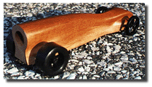 With a CNC machine doing the carving, cars come out perfectly bilateral and even the wildest designs can achieve the "concept car" look. Students want these cars, and they know that winning this activity depends more on their minds than their hands. Fortunately, technology has advanced to a point where students can delegate laborious manual tasks to a machine. Producing high-quality projects no longer requires superior dexterity. Also, if the C02 competition is a public event, the sharp appearance of high-tech race cars will give a good impression to parents and the public. More than 50 middle and high school technology education programs in south Florida have converted to building C02 race cars with CAD/CAM/CNC, using Techno’s IMS C02 system. With the system, students can produce C02 metric 500 cars in less than an hour. The cars not only satisfy Technology Student Association (TSA) specifications, but they also have placed high in state, regional, and national competitions. In the 1996 TSA national competition, juniors with CAD/CAM/CNC cars placed first and third. A highly motivated and enthusiastic special education student took fourth place. In the 1997 competition, four CAD/CAM/CNC-produced cars placed in the top 10, with one taking first place. Background: The concept of producing C02 cars with CAD/CAM/CNC has been possible for years, though not plausible. CAD systems could describe complex 3-D shapes, but it took too long to get a student up to speed to draw a car. CAM systems could generate the toolpath, but problems 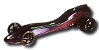 CNC machines could cut a car, but slow feeds and speeds made the process so time consuming that not everyone in the class could use it. No text existed for guiding students through all of the integrated processes. Three companies, CNC Software (Mastercam), Techno, and IMS Technologies have worked together to address these challenges. The technology has come of age and pricing has fallen to under $10,000 for a complete system. One package can process an entire class, though some instructors add additional software stations to allow more experimentation with design. 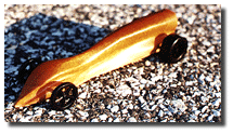 After all the cross sections are drawn, the part is mirrored to complete the design and then rendered. The rendered image lets the student check the design form and determine whether it meets TSA specifications. A window is put around the cross sections and the toolpath is generated. The generated toolpath is for the right side of the car. This toolpath is mirrored to produce the left-side toolpath. Two toolpaths are necessary as the car is cut from the right side then indexed to the left side. Precision indexing is the key to cutting the car from the side. The fixture. A fixture is integral to the success of this process. Cutting the car from the side eliminates cutter burial problems, and the fixture addresses indexing problems. The C02 canister hole on the blank is placed on a shaft on the back of the fixture, and the shaft is pushed forward. The front of the blank fits in a holder on the front of the fixture. A few taps with a soft-blow hammer secures the blank. The car is machined on one side, then the fixture is loosened, indexed 180, and the other side is machined. This produces a bilaterally perfect car.
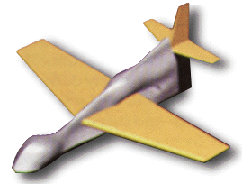
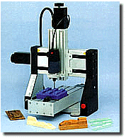
The curriculum. The IMS C02 curriculum integrates all aspects of the procedure from machine and fixture setup to software instructions. Students and teachers receive instructional training videos and curriculum guides, step-by-step instructions for assemble and use, clamps, fixtures, and software. The basic system includes CAD software. CAM toolpath generation software, and a CNC machine. The CAM software eliminates hand carving by creating tooling instructions for the CNC machine, based on the CAD drawing specifications. The three-axis CNC machine performs the manual labor with precision, speed, and reliability. The only manual work left for students is finishing touches, such as light sanding, painting the car, and adding wheels. This approach saves students time and lets them focus on learning new skills and experimentation. The speed of the CNC machine also allows students to produce more than one race car, experimenting with different materials and designs and testing aerodynamic differences. This freedom to experiment encourages innovative thinking, creative problem solving, and collaborative brainstorming efforts. This activity results in students learning transferable skills by using the same prototype and design software and machines found in high-tech industrial workplaces. Students also benefit from having the luxury of performing trial-and-error learning and discovery. Other options. Advanced secondary students can go beyond defining their cars with simple cross-sectional slices. Cars can be designed using full surface modeling, which allows for greater detail and more variation in shape. Students might also take on the engineering challenge of designing a car/boat/plane body. Here, they would take into consideration the particular requirements of each type of vehicle: 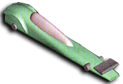
 |
 Techno is celebrating over 25 years of CNC technology
expertise. Our Educational sector provides industrial quality products
at educational prices with a network of award-winning Educators. We can
provide CNC Curriculums, CNC Projects, Technical Information and
Packages for any educational classroom.
 Although this activity has proved motivational and
successful, it can be improved by updating the design and
production process with CAD/CAM/CNC (computer-aided
drafting/computer-aided manufacturing/computer numerical control).
This approach teaches the skills needed in high-tech manufacturing
careers and stimulates student interest.
 Boat – The
first consideration is hydrodynamic shape (water flow), then the
amount of water the shape displaces, then the placement of the
mast. The boat competition would use the same C02 body,
with a spent C02 cartridge as ballast. A mast hole
would be drilled into the bottom of the car to hold a standard
sail. The race would take place in a vinyl rain gutter filled with
water, and the student would provide power with air from a
portable fan. Points would be awarded for speed and straightness
of course.